BellMe — Saving Lives
Duty station display panel · Voerka W900

B-901 Display Panel

A nurse call systems duty station display panel for high-capacity installations, software-managed reporting, LAN-connected setup and 16-character calling information.

Button capacity
3000
Display
Ward A/Bed 12
Software
W900
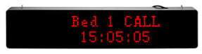
BellMe B-901 display panel showing red LED text and time on a black duty station display
LAN display · gateway · PC
Call and cancel reports

Key features

Capacity, software reporting, display behaviour and cancellation options for the B-901 system.

3000

Nurse call button capacity

Up to 3000 nurse call buttons can be programmed to this display panel. Depending on the number of nurse call buttons required, the respective capacity software will be activated.

W900

Desktop software

Works in conjunction with the W-900 Desktop Software, allowing you to view and extract reports that indicate the call and cancel times of the nurse call buttons.

16

16-character display

Display information allows for up to 16 characters. The characters may be aliphatic, numerical, or a combination of the two — for example, “Ward 5 Bed 1”.

Hold

Display time

When a nurse call button is pressed, the calling information remains on the duty station display panel until the cancel button is pressed, or until the call is automatically cancelled depending on your settings.

Auto

Auto-cancel

If you do not wish to use cancel buttons, the duty station display panel can be set to cancel calls automatically after your chosen period of time.

Requirements

The B-901 system requires software, network access and wired LAN connections during operation and programming.

01

A dedicated laptop or PC to run the software. The laptop or PC must be able to install and run Windows 10 or 11 in order to support the software.

02

A constant and stable internet connection.

03

A router with at least 4 available ports to run LAN cables.
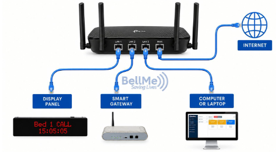
Initial setup diagram: a router connected by LAN cables to the display panel, smart gateway and computer or laptop, with internet access
Initial setup: connect the display panel, smart gateway and PC or laptop to the router via LAN cable.

Setup guide

Follow the setup flow from connecting the hardware to adding buttons and mapping areas in Voerka W900.

01

Initial setup

  1. 01Plug in the display panel.
  2. 02Plug in the gateway.
  3. 03Connect the display panel to your internet router via LAN cable.
  4. 04Connect the gateway to your internet router via LAN cable.
  5. 05Connect your PC or laptop to your internet via LAN cable.
  6. 06Open the new display panel software: Voerka W900.
  7. 07Log into the software with the default username admin and password 123456.
  8. 08You will notice the time and date on the display panel is now correct.
02

Activate the software

Activate the software using the activation code received.

  1. 01Log into the software.
  2. 02Go to Activation.
  3. 03Click on Activate Online.
  4. 04Complete the information fields.
  5. 05Click on Submit.
Important note. You cannot use the same activation code for more than one computer. If you want to change the computer that holds the software, you would need to purchase a new activation code.
03

Authorize the display panel and gateway

On the software, go to Device Center.

  1. 01Click on Device Discover.
  2. 02Click on Start Scan.
  3. 03You will notice the display panel and the gateway serial numbers appear.
  4. 04Tick them both and click on Authorize.
  5. 05You will notice a pop-up showing Success.
04

Check device details

Go to Device Manage.

  1. 01You will notice the display panel and the gateway show Online.
  2. 02Double-click on each device to show the details and make any edits.
  3. 03Ensure that the IP for the display panel and the gateway are not the same.
Important note. The programming must be done using the IP address of the PC or laptop that will be running the software.
05

Adding buttons

Go to Device Discover.

  1. 01Click on Start Scan. You can tick the box to Ignore Authorized.
  2. 02Once it is scanning, press the call button you want to add.
  3. 03The call button serial number and information will appear.
  4. 04Click Stop Scan, select the button, and click Authorize.
  5. 05Add the buttons one by one, because once they are discovered there is no way to tell them apart.
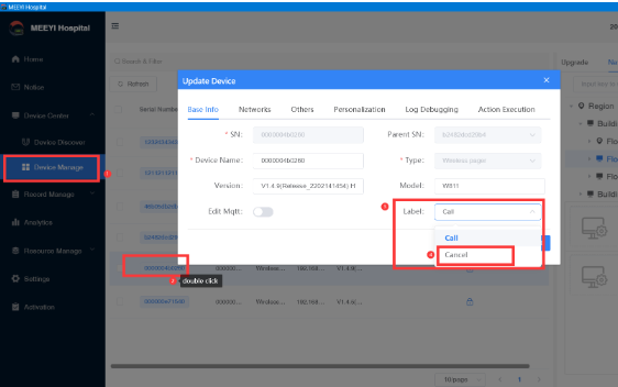
  6. 06As you add each one, go to Device Manage and rename the button by double-clicking on it and changing the device name.
  7. 07When adding cancel buttons, adjust the label to indicate cancel instead of call.
06

Linking devices to areas

  1. 01Click on Device Manage.
  2. 02Click on Navigation on the right to edit and build your layout by adding and editing nodes.
  3. 03Pull the gateway and the display under your main area.
  4. 04Drag the serial number from the list to the box on the bottom right.
  5. 05Once it is in place, a lock appears under Node Bound to indicate that those devices have been linked.
  6. 06Pull your buttons to each location on your created layout accordingly.
  7. 07All buttons added onto any areas falling under your main area will now be linked to the display and gateway.
  8. 08Once you have all devices pulled into place, click on Configure Mapping Area.

Useful video guides

Direct guides for setup, linking devices, building layouts, programming buttons and changing settings. Click any video to watch it right here.
Useful image guides

Software screenshot guide: How to change the label for a cancel button
Guide 01

How to change the label for a cancel button

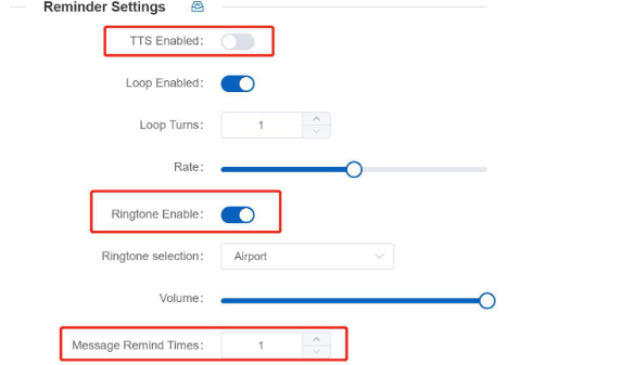
Software screenshot guide: How to set interval ringing
Guide 02

How to set interval ringing

Software screenshot guide: How to set auto cancel
Guide 03

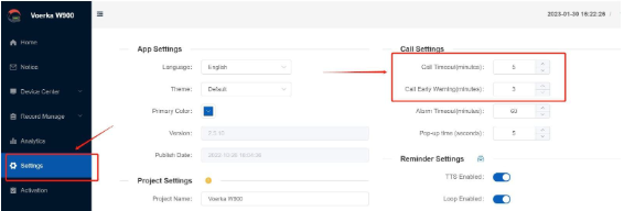
How to set auto cancel

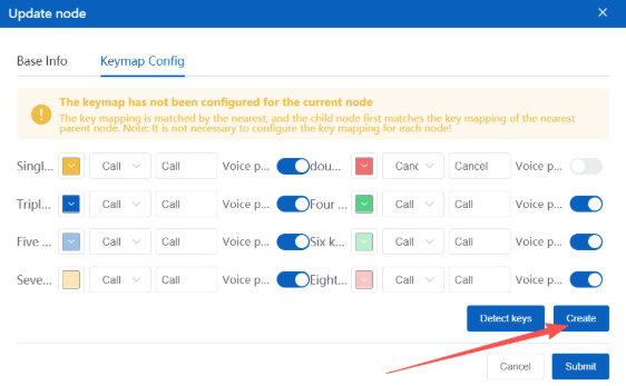
Calling information not coming up? If the calling information is not coming up on the software or display panel while the gateway and display panel are online, make sure a key-value mapping at the primary node was created or updated.
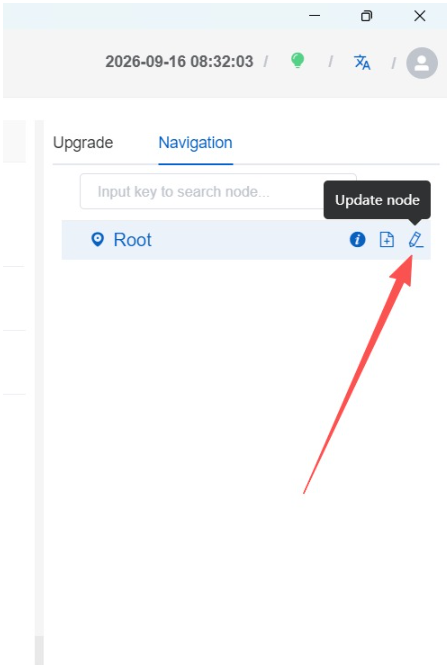
Key-value mapping guide, step 1 screenshot: In Device Manage, open the Navigation tab, then click the edit icon on the Root node to open Update node.
Step 01

In Device Manage, open the Navigation tab, then click the edit icon on the Root node to open Update node.

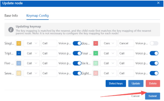
Key-value mapping guide, step 2 screenshot: In Update node, open the Keymap Config tab. If the keymap has not been configured for the node, click Create.
Step 02

In Update node, open the Keymap Config tab. If the keymap has not been configured for the node, click Create.

Key-value mapping guide, step 3 screenshot: Set or update the key mapping, click Update, then click Submit to save the keymap for the node.
Step 03

Set or update the key mapping, click Update, then click Submit to save the keymap for the node.

Other questions & answers

Can you have different ringtones for different buttons?

No, you cannot. One ringtone is selected for all buttons from all areas.

Can you use the software without a display panel?

Yes, you can use the Voerka Software and the Smart Gateway without the display panel. You cannot use the B-901 display panel without the smart gateway and Voerka Software.

Will our signal repeaters still work with the gateway and display?

Yes, you can add signal repeaters to extend the range of the system.

Can the system work without internet?

The system requires internet to be programmed and cannot work without being connected via a network.

How do I fix it when the gateway and display are showing offline?

Check the IP addresses. The gateway and display panel should not have the same IP address. If they are the same, change one of them. You can also try a different version of the software if it does not come right.

If I have 2 call buttons and 1 cancel button, does the calling information for both call buttons still have to be the same if I want them to share the one cancel?

No, you can now have multiple call buttons with different calling information and cancel them with one cancel.

If you purchase the software once, can it be used on multiple PCs?

No, if you want the software to be used on multiple computers, you need to purchase the software for each PC.

What should I do if the display panel does not pick up on the software when scanning?

Press and hold the reset factory settings button for 8 seconds. The network interface light where the LAN cable is plugged in will go off and on again once the reset has been successful.

What should I do if the display panel is showing the incorrect time even though it is online?

Press and hold the reset factory settings button for 8 seconds. The network interface light where the LAN cable is plugged in will go off and on again once the reset has been successful.

How do I save a backup file?

In the software, under Settings, go to Database Backup and Open Folder. Copy the prod file. This is the backup.

How do I load a backup file onto a new display panel?

In the software, under Settings, go to Database Backup and Open Folder. Replace the prod file.

What should I do if the calling information is not displaying correctly when a button is pressed?

Make sure that you are not using more than 16 characters. If it is still not showing correctly, unbind the button and delete the node, then add the node again and bind the button again.